Managing DMF Switches and Interfaces
This chapter describes the basic configuration required to deploy and manage DANZ Monitoring Fabric (DMF) switches and interfaces.
Overriding the Default Configuration for a Switch
- Info
- Clock
- SNMP
- SNMP traps
- Logging
- TACACS
- sFlow
- LAG enhanced hash
CLI Configuration
config-switch submode.
controller-1(config)# switch <switch-name>controller-1(config)# switch DMF-SWITCH-1
controller-1(config-switch)#From this submode, you can configure the specific switch and override the default configuration pushed from the DANZ Monitoring Fabric (DMF) Controller to the switch.
The DANZ Monitoring Fabric 8.5 Deployment Guide provides detailed instructions on overriding the switch's default configuration..
DMF Interfaces
- Filter interfaces: ports where traffic enters the DMF. Use filter interfaces to TAP or SPAN ports from production networks.
- Delivery interfaces: ports where traffic leaves the DMF. Use delivery interfaces to connect to troubleshooting, monitoring, and compliance tools. These include Network Performance Monitoring (NPM), Application Performance Monitoring (APM), data recorders, security (DDoS, Advanced Threat Protection, Intrusion Detection, etc.), and SLA measurement tools.
- Filter and delivery interfaces: ports with both incoming and outgoing traffic. When placing the port in loopback mode, use a filter and delivery interface to send outgoing traffic back into the switch for further processing. To reduce cost, use a filter and delivery interface when transmit and receive cables are connected to two separate devices.
- Service interfaces: interfaces connected to third-party services or network packet brokers, including any interface that sends or receives traffic to or from an NPB.
In addition, interfaces connected to managed service nodes and DANZ recorder nodes can be referenced in the configuration directly without assigning a role explicitly. Also, Inter-Switch Links (ISLs), which interconnect DANZ monitoring switches, are automatically detected and referred to as core interfaces.
Using the GUI to Configure a DMF Filter or Delivery Interface
- Select from the main menu to display the DMF interfaces.
Figure 1. DMF Interfaces 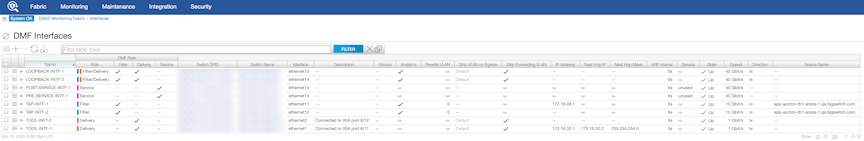
- Click the provision control (+) in the Interfaces table to configure a new interface.
Figure 2. Create Interface 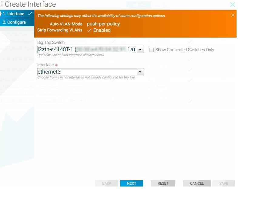
- Select a radio button to assign a role to the interface:
- Filter
- Delivery
- Filter and Delivery
- Service
Note:- The options available are updated based on the selection.
For example, when selecting Filter, the system displays the following dialog box.
Figure 3. Create Interface: Filter 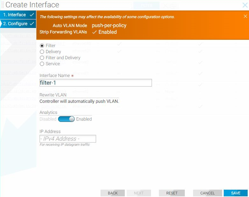
- Analytics is enabled by default. To disable Analytics for the interface, move the slider to Disabled. For information about Analytics, refer to the Analytics Node User Guide.
- Optionally, enable the Rewrite VLAN option for a filter or a filter and delivery interface.
- Enable the Rewrite VLAN option when configuring a Filter interface by identifying the VLAN in the Rewrite VLAN field.
Using the CLI to Configure a DANZ Filter or Delivery Interface
Using the CLI to Identify a Filter Interface using Destination MAC Rewrite
Global Configuration
Configure this function at the filter interface level and perform the following steps using the CLI.CLI Show Commands
The following show command displays the ingress flow for the filter switch.
In the Entry value column, the filter switch contains dst MAC tlv: EthDst(00:00:00:00:00:03).
(config-policy)# show switch filter1 table ingress-flow-2
# Ingress-flow-2 Device name Entry key Entry value
-|--------------|-----------|---------------------------------------|-----------------------------------|
1 0filter1 Priority(6400), Port(5), EthType(34525) Name(p1), Data([0, 0, 0, 61]), PushVlanOnIngress(flags=[]), VlanVid(0x1), Port(1), EthDst(00:00:00:00:00:03)
2 1filter1 Priority(6400), Port(5) Name(p1), Data([0, 0, 0, 62]), PushVlanOnIngress(flags=[]), VlanVid(0x1), Port(1), EthDst(00:00:00:00:00:03)
3 2filter1 Priority(36000), EthType(35020) Name(__System_LLDP_Flow_), Data([0, 0, 0, 56]), Port(controller), QueueId(0)
The core and delivery switch in the Entry value column doesn’t contain dst MAC tlv, as shown in the following examples.
(config-policy)# show switch core1 table ingress-flow-2
# Ingress-flow-2 Device name Entry key Entry value
-|--------------|-----------|-----------------------------------------------------|----------------------------|
1 0core1 Priority(6400), Port(1), EthType(34525), VlanVid(0x1) Name(p1), Data([0, 0, 0, 60]), Port(2)
2 1core1 Priority(6400), Port(1), VlanVid(0x1) Name(p1), Data([0, 0, 0, 59]), Port(2)
3 2core1 Priority(36000), EthType(35020) Name(__System_LLDP_Flow_), Data([0, 0, 0, 57]), Port(controller), QueueId(0)
(config-policy)# show switch delivery1 table ingress-flow-2
# Ingress-flow-2 Device name Entry key Entry value
-|--------------|-----------|-----------------------------------------------------|----------------------------|
1 0delivery1 Priority(6400), Port(1), EthType(34525), VlanVid(0x1) Name(p1), Data([0, 0, 0, 64]), Port(6)
2 1delivery1 Priority(6400), Port(1), VlanVid(0x1) Name(p1), Data([0, 0, 0, 63]), Port(6)
3 2delivery1 Priority(36000), EthType(35020) Name(__System_LLDP_Flow_), Data([0, 0, 0, 58]), Port(controller), QueueId(0)Troubleshooting
To troubleshoot the scenario where the provided destination MAC address is attached incorrectly to the filter interface. The ingress-flow-2 table above will have a destination MAC rewrite tlv on the filter switch, but no such tlv appears on the core or delivery switch.
As an alternative, drop into the bash of the filter switch to check the flow and destination MAC rewrite.
Use the following commands for the ZTN CLI of the filter switch.
(config)# connect switch filter1
(ztn-config) debug admin
filter1> enable
filter1# debug bash
The following command prints the flow table of the filter switch.
root@filter1:~# ofad-ctl gt ING_FLOW2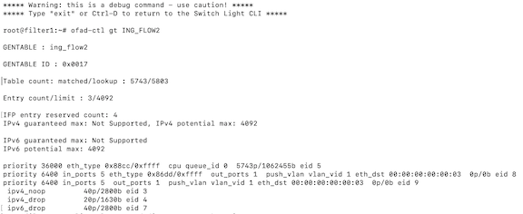
(config)# show policy-flow
# Policy Name SwitchPkts Bytes PriT MatchInstructions
-|-----------|-----------------------------------|----|-----|----|-|------------------------|------------------|
1 p1core1 (00:00:52:54:00:15:94:88) 00 6400 1 eth-type ipv6,vlan-vid 1 apply: name=p1 output: max-length=65535, port=2
2 p1core1 (00:00:52:54:00:15:94:88) 00 6400 1 vlan-vid 1 apply: name=p1 output: max-length=65535, port=2
3 p1delivery1 (00:00:52:54:00:00:11:d2) 00 6400 1 vlan-vid 1 apply: name=p1 output: max-length=65535, port=6
4 p1delivery1 (00:00:52:54:00:00:11:d2) 00 6400 1 eth-type ipv6,vlan-vid 1 apply: name=p1 output: max-length=65535, port=6
5 p1filter1 (00:00:52:54:00:d5:2c:05) 00 6400 1apply: name=p1 push-vlan: ethertype=802.1Q (33024),set-field: match-field/type=vlan-vid, match-field/vlan-tag=1,output: max-length=65535, port=1,set-field: match-field/eth-address=00:00:00:00:00:03 (XEROX), match-field/type=eth-dst
6 p1filter1 (00:00:52:54:00:d5:2c:05) 00 6400 1 eth-type ipv6apply: name=p1 push-vlan: ethertype=802.1Q (33024),set-field: match-field/type=vlan-vid, match-field/vlan-tag=1,output: max-length=65535, port=1,set-field: match-field/eth-address=00:00:00:00:00:03 (XEROX), match-field/type=eth-dst
Considerations
- The destination MAC rewrite cannot be used on the filter interface where timestamping is enabled.
- The destination MAC rewrite will not work when the filter interface is configured as a receive-only tunnel interface.
Using the GUI to Identify a Filter Interface using Destination MAC Rewrite
Workflow One: Using either the (or the ) page, proceed to the following workflow:
Create Interface
- Select the Filter radio button for the interface and use the Rewrite Dest.MAC Address input to configure the MAC address to override.
Figure 5. Create Interface 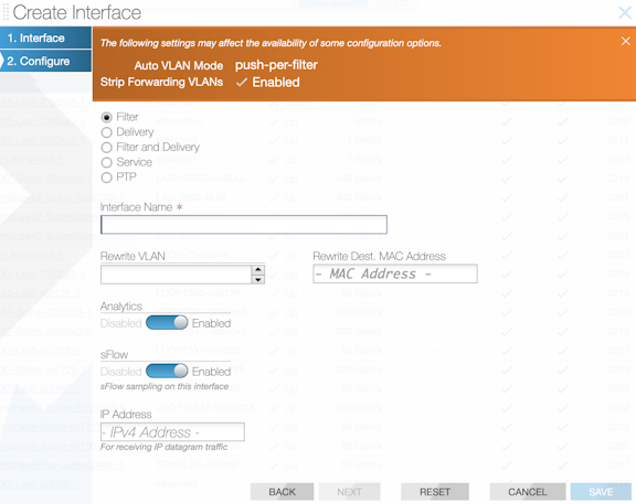
Edit Interface
- Select the row menu of the filter interface to configure or edit, and select Edit.
Figure 6. DANZ Monitoring Fabric (DMF) Interfaces - Edit 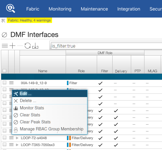
Workflow Two: When using the page, use the following workflow:
- Select the row menu of the switch interface associated with the filter interface you want to configure and select Configure.
Figure 7. Configure Interface 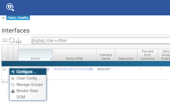
- In the DMF tab, select the Rewrite Dest.MAC Address field to enter the MAC address to be overridden.
Figure 8. Edit Interface DMF Rewrite Dest. MAC Address 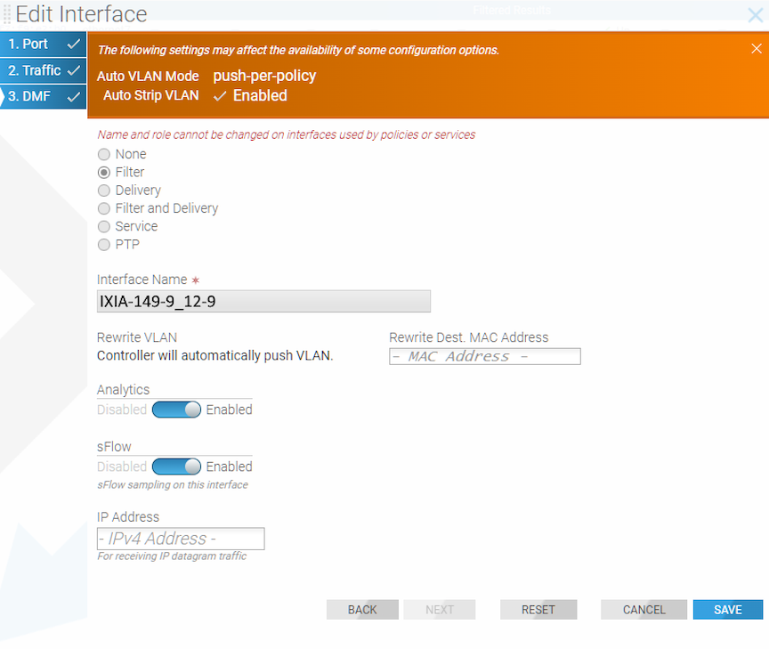
Using Interface Groups
Create an interface group consisting of one or more filter or delivery interfaces. It is often easier to refer to an interface group when creating a policy than to identify every interface to which the policy applies explicitly.
Use an address group in multiple policies, referring to the IP address group by name in match rules. If no subnet mask is provided in the address group, it is assumed to be an exact match. For example, in an IPv4 address group, the absence of a mask implies a mask of /32. For an IPv6 address group, the absence of a mask implies a mask of /128.
Identify only a single IP address group for a specific policy match rule. Address lists with both src-ip and dst-ip options cannot exist in the same match rule.
Using the GUI to Configure Interface Groups
- Select the option.
Figure 9. Creating Interface Groups from Monitoring > Interfaces
Using the CLI to Configure Interface Groups
controller-1(config-switch)# filter-interface-group TAP-PORT-GRP
controller-1(config-filter-interface-group)# filter-interface TAP-PORT-1
controller-1(config-filter-interface-group)# filter-interface TAP-PORT-2
controller-1(config-switch)# delivery-interface-group TOOL-PORT-GRP
controller-1(config-delivery-interface-group)# delivery-interface TOOL-PORT-1
controller-1(config-delivery-interface-group)# delivery-interface TOOL-PORT-2
To view information about the interface groups in the DMF fabric, enter the show filter-interface-group command, as in the following examples:
Filter Interface Groups
controller-1(config-filter-interface-group)# show filter-interface-group
! show filter-interface-group TAP-PORT-GRP
# Name Big Tap IF NameSwitch IF NameDirectionSpeed State VLANTag
-|------------|--------------------------|-----------------|----------|---------|-------|-----|--------|
1 TAP-PORT-GRP TAP-PORT-1 DMF-CORE-SWITCH-1 ethernet17rx 100Gbps up0
2 TAP-PORT-GRP TAP-PORT-2 DMF-CORE-SWITCH-1 ethernet18rx 100Gbps up0
controller1(config-filter-interface-group)#controller1(config-filter-interface-group)# show delivery-interface-group
! show delivery-interface-group DELIVERY-PORT-GRP
# NameBig Tap IF Name Switch IF NameDirectionSpeed Rate limit State Strip Forwarding Vlan
-|-----------------|---------------|---------------------|----------|---------|------|---------|-----|---------------------|
1 TOOL-PORT-GRP TOOL-PORT-1 DMF-DELIVERY-SWITCH-1 ethernet15 tx10Gbps upTrue
2 TOOL-PORT-GRP TOOL-PORT-2 DMF-DELIVERY-SWITCH-1 ethernet16 tx10Gbps upTrue
controller-1(config-filter-interface-group)#